Monday, September 28, 2009

Libraries for Hope RFM12 RF Modules

I've had a few of the popular RFM12 ISM Transceivers lying around for quite some time, and am finally using them for a project now.
The bad thing about them is their poor documentation, so I've been looking around for a finished & working library to use with them.

I've bought modules from
www.neuhold-elektronik.at and
www.pollin.de

Libraries:
Lib by Benedikt K. simple, low level, works well. Written for AVRs using avr-gcc; Bascom and PIC versions exist as well.
bla repository Sports CRC, high level API
Strobotics
Das Labor
Codevision C

Read more...

Friday, April 10, 2009

Free Software for PCB Milling


Most of us are propably either using perfboards or a breadboard/PCB etching combination to build electronic circuits. Especially perfboards are a great choice for beginners and intermediate hobbyists, and i've used them myself for years, but at some point soldering all those wires onto the board starts to suck.
Due to their cost, CNC mills and routers are still pretty scarce even amongst dedicated hardware hackers, but it's just great to be able to create your own fairly high-quality PCBs quick and without too much effort.
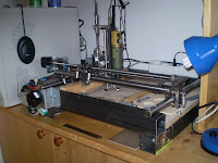
This article lists free software i am using to mill circuit boards on my home-built gantry router.

Schematic and layout

First of all, you usually need to draw a schematic.
Many hobbyists seem to use Eagle, but it's proprietary.
On the free software side, there are mainly Kicad and GNU EDA.
While Kicad comes with it's own layout editor, gEDA relies on UNIX pcb and an easy to use converter tool (gsch2pcb).
All those programs (including eagle) are available through the ubuntu repositories.
I am currently using gEDA/PCB, which is a well working combination IMO.

Calculating toolpaths

After you've finished your layout, you need to calculate toolpaths for your CNC machine. If you are using Kicad or gEDA, you have to export Gerber (RS-274X) files instead of generating RS-274NGC G-Codes directly. To convert those to G-Codes, I recommend using pcb2gcode, a command-line tool in the development of which i am currently actively involved in. Be sure to try the gerbv branch first. Alternatively, gCam is a sound choice (GUI, bit buggy).

Update: The pcb2gcode gerbv branch is now in trunk.

There's more info on the mechanical part of PCB milling and Eagle on millpcbs.com.

More pictures here

Read more...

Thursday, March 5, 2009

Another DIY CNC router, Pt. 1: Software, Electronics

Small CNC mills and routers can be a bless for the dedicated tinkerer, but they're expensive, to say the least. No wonder there have been lots of efforts in home-built ones.
Anyway, this is how my dad and i built ours. It's mainly used to isolation route, drill and cut out single- and double-sided circuit boards, but also for engraving signs and milling small aluminium parts.

First, i will show you how to connect unipolar stepper motors to your computer and set up the necessary software.


Setting up EMC2

Many DIY and commercal mills use EMC, the enhanced machine controller. It's free, linux based and as flexible as it could ever be.
The very best way to get and set up EMC2 is to use the Ubuntu EMC2 Live CD. You can try to install it yourself (did that with 6.10), but i tell you, it's a pain.

When you run EMC2 for the first time, you will be asked to choose a configuration. You can pick either stepper_mm or stepper_inch and tell EMC to copy it to your home directory for customization. Download this archive and choose one of the supplied setups (you can switch between them at any time):

2.5D (2 unipolar stepper motors, servo for Z)
3D (3 unipolar stepper motors)

Each setup comes with two .hal-Files. Overwrite the original files of your configuration with these and you're done.


Building a simple Stepper Driver

The next thing you will need are two unipolar stepper motors with up to 250mA current/phase. I bought mine from Pollin
(Howard Industries 1-19-4200), but you might as well salvage ones from old printers.
To drive them, i recommend using the circuit displayed below - it's dirt cheap and really simple, but still sufficient for now. Connect the stepper's common wires to Pin 1 and 2 of the respective connector and the others to the rest. It will propably take you a few tries to find out the correct order.

Hints:
  • Use an ohmmeter to identify the steppers common wires and corresponding coil ends.
  • You can change the pinout in the configuration's standard_pinout.hal.
  • Old printer's axes can be used as a great testing machine.
  • Use an old computer power supply to power the driver.
  • For now, it doesn't matter which HAL files you have chosen.


You should be able to make 2 steppers run now. If you've got problems, just ask.

There may be quite a few posts on this topic in the next weeks, mainly concerning a few details of the mechanical construction, but probably only on request.

UPDATE: Ok, I won't write anything about the mechanical part. Most of the good stuff is already documented elsewhere anyway, e.g. the linear bearings are similar to those.


Read more...

Monday, March 2, 2009

DIY ColdHeat-like Soldering Tweezers

Ever tried one of those fancy "Cold-Heat" soldering iron replacements?
I did, and i really liked my Cold-Heat Classic after i got used to it, but then it's cheap crappy electronics died.
Since it's quite limited when it comes to soldering small parts, i tried to find a better solution.

The result is pretty similar to this thingie (read first),
except that i've picked up his idea of building tweezers to be able to adjust the spacing of the leads.
It's quite a failure, but building it was fun.

I just twisted .5 mm² wire end sleeves using pliers until they firmly held .7 mm leads, then soldered them onto old steel tweezers, isolated the halves from each other and applied 5V from an old computer power supply to it. Be aware that this will draw around 8 A, so use thick wires. It's actually a bit too powerful, which is why you have to be quite fast if you don't want to burn all the flux before your soldering connection is nicely set (see the video). Also, make sure that the leads can't touch each other, if they do they will just burn up without sufficiently heating the tin.


UPDATE: Don't try to solder SMD parts using this. Crap.
UPDATE2: Using a current source would definitely work much better given that the lead's resistance falls with temperature, but that's far too much effort for my taste.

Read more...

Friday, February 20, 2009

Where to source tools and components in Austria

This is a short list of online stores i like. I live in Austria, but most of them ship to everywhere in the EU. Some sites may be available in german only.

Retailers
CSD Electronics - Very good prices e.g. on some Atmel Microcontrollers
DealExtreme - Chinese online shop, wide range of cheap, but also quality stuff
HobbyKing
- RC parts & models, brushless motors, ESCs, Accus, etc. Great CA glue!
Distrelec - comparatively cheap for low volume orders. fast delivery
Conrad - expensive. high quality tools, lots of odd components
mylemon.at - computer parts
CNCShop.at - linear guides, acme thread rods + nuts
e-MadeinCHN - cheap RF modules, worldwide shipping

Surplus Stores
Pollin Elektronik - very cheap, tons of great stuff; shipment can take weeks
Neuhold Elektronik


Also, there are long and comprehensive lists of part sources at roboternetz.de and elektronik-kompendium.de.


Read more...

Hacking a digital alarm clock

First of all, this particular hack i did a few weeks ago to make my alarm clock enable external circuits is similar to this one that was featured on hackaday. If you think about building one of them yourself i recommend the other one - it's just a bit more expensive, but much more versatile.

Both basically work the same way: The speaker/buzzer driver of the mobile phone/alarm clock is used to trigger a thyistor. I just used TO92 general purpose transistors i had lying around.
Depending on what kind of signal source you intend to use, you should be able to omit the diode and maybe the capacitors if the resistors are small enough.
Anyway, it's best not to build a discrete thyristor like i did but use a "real" one.
Note that the thyristor will remain latched until you remove the load (e.g. using a switch).

Read more...